Architectural Models for Manufacturing Facility Expansion
How detailed architectural models help manufacturers visualize facility expansions, streamline stakeholder approval, and prevent costly construction errors in East Africa.
See everything Moriasi3D Models can do for you.
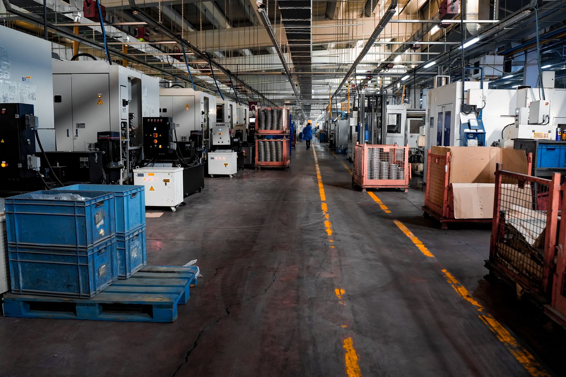
When a manufacturing facility expands, the decisions made on paper before a single column is poured can determine whether the project succeeds or struggles for years afterward. A physical architectural model brings those decisions into three dimensions, giving engineers, factory managers, and investors a shared object they can all stand around and actually see. At Moriasi3D Models, we have worked on industrial and commercial projects across East Africa long enough to know that a well-built facility model is not a luxury for large clients alone. It is one of the most practical tools available to any business planning a serious expansion.
This article is part of our complete guide: Architectural Models for Houses.
Why Manufacturing Facilities Need Physical Models
Production floor layout visualization before construction begins
A manufacturing floor is one of the most spatially complex environments an architect or engineer will ever design. Equipment sits at specific heights, requires precise clearances, and must align with feeding lines and output conveyors in a logical sequence. When that arrangement exists only in a CAD file, it is genuinely difficult for non-technical stakeholders to picture what daily operations will feel like inside the finished building. A physical model translates those coordinates into something a factory manager can lean over and understand in minutes. That shared understanding, reached early, is where good expansion decisions begin.
Identifying workflow bottlenecks and equipment placement issues early
Bottlenecks in a production line almost always have a spatial origin: a conveyor that turns too sharply, a forklift aisle that narrows at a critical junction, or two large machines competing for the same floor zone. These problems are surprisingly hard to catch on a flat drawing, because the human eye reads a plan view differently from the way a body moves through a real space. A scale model forces every element to occupy its actual proportionate footprint, making clashes visible before a concrete slab has been poured. Catching one such conflict at the model stage typically costs a fraction of what a field modification costs once steel is up. Early discovery is where the model earns its cost back quickly.
Helping factory managers and engineers understand spatial relationships at a glance
Factory managers live in operational logic, not architectural notation. When you hand a senior production supervisor a 1:100 model of the proposed expansion, they can immediately locate the incoming goods area relative to the assembly stations and trace the path a finished product will travel to dispatch. That kind of intuitive reading is nearly impossible with drawings alone, even for experienced staff. Engineers benefit too, because a model exposes elevation changes, mezzanine relationships, and roof clearances that are easy to misread across multiple drawing sheets. Shared spatial understanding leads to sharper questions and better decisions in every project meeting.
Reducing expensive design revisions once construction has started
Design changes during construction are one of the most predictable sources of cost overrun in industrial projects. A contractor who has to reroute a structural beam or relocate a drainage channel after the slab is cast will charge accordingly, and the delay ripples through the entire programme. A physical model reviewed thoroughly before tender documents are issued gives every party a concrete reference that reduces ambiguous interpretations. Architects, mechanical engineers, and site managers are all looking at the same three-dimensional object when they agree on an approach. That agreement is what protects your budget at the construction stage.
Key Elements to Include in Your Facility Model
Accurate equipment footprints and machinery clearances
Every major piece of production equipment should be represented in the model at its actual scaled footprint, including the maintenance clearance zones that safety regulations require around it. This is not about visual effect; it is about ensuring that the floor plan actually works when real machinery arrives on site. We model equipment blocks using your supplier specifications or general arrangement drawings, so the clearances shown are specific to your machines rather than generic approximations. Overlooking a clearance zone at this stage is exactly the kind of error that forces an expensive floor modification later. Precision at this step protects the whole downstream process.
Utility routing for power, water, and compressed air lines
Industrial facilities depend on dense utility networks, and routing those networks efficiently is a significant design challenge. Power trunking, compressed air headers, process water pipework, and drainage all need to reach equipment without obstructing access routes or creating hazards. Including simplified utility routing in a facility model lets your mechanical and electrical teams verify that their systems are coordinated before drawings are issued for tender. Even a schematic representation of major runs is more useful than none, because it reveals spatial conflicts between services and structure early. A model that shows the building shell without its utilities is only telling half the story.
Loading dock and material flow pathways
The loading dock is the lung of a manufacturing facility, and its relationship to internal material flow paths deserves careful modelling. Your model should show the dock apron, levelling equipment, and the first internal bay clearly enough that a logistics manager can trace a pallet from truck to storage to production line without lifting a finger from the model surface. Turning radii for forklifts and articulated trucks should be indicated at the correct scale, because tight yard layouts in Nairobi industrial parks can make manoeuvring a genuine constraint. Material flow pathways modelled in colour or with directional indicators make the logic of the operation immediately readable. Getting this right at the model stage prevents costly yard reconfiguration later.
Structural elements like columns, mezzanines, and roofing systems
Columns interrupt floor space in ways that drawings undersell. A mezzanine that looks elegant in section can create uncomfortable low headroom zones that a model exposes immediately. Representing the structural grid, mezzanine decks, and roof profiling in the model gives everyone a realistic sense of the envelope they are working within. For manufacturing facilities with overhead cranes, the hook height and crane beam should appear in the model because they constrain every tall machine that will operate beneath them. Structural honesty in the model prevents optimistic assumptions from surviving into the construction phase.
Access points for maintenance and worker safety
Safe access for maintenance is a regulatory requirement and an operational necessity, yet it is frequently under-represented in early design models. Your facility model should show personnel doors, emergency exits, stair towers, and any access platforms required to reach elevated equipment. Worker flow paths to amenities like ablutions and rest areas should be traceable without passing through active production zones, which is a requirement under most industrial safety frameworks. Modelling these access routes makes it straightforward to verify compliance visually rather than through calculations alone. Safety reviewers, including those from the relevant Kenyan authorities, respond well to a model that answers their questions before they ask them.
Scale and Detail Considerations for Industrial Projects
Choosing the right scale to show both overall layout and critical details
Scale selection for a manufacturing facility model is a genuine technical decision rather than an aesthetic preference. A 1:200 scale is appropriate for communicating overall site organisation and building footprint to a board or planning authority, but it is too small to show equipment clearances meaningfully. A 1:100 or 1:50 scale brings machinery and workflow into readable focus but may make a large facility unwieldy to transport and store. In practice, the right answer often involves a master site model at a smaller scale combined with one or two detailed sectional models at a larger scale for the most complex zones. We discuss this balance with clients at the outset so expectations around size, cost, and purpose are aligned.
Sectional models that reveal internal systems without losing external context
A sectional model, where one wall or roof panel is removable or the building is cut through at a meaningful plane, is particularly valuable for multi-storey or mezzanine-heavy industrial designs. It lets a viewer see internal equipment arrangement, service routing, and vertical relationships while still understanding the external building form. For a facility with a high-bay production hall alongside a lower-level office or welfare block, a section cut through the junction of those two volumes tells the design story clearly. Removable roof panels are a practical alternative that preserve the external model while allowing access to the interior for detailed inspection. The right sectional strategy depends on which internal systems carry the most decision-making weight.
Material finishes that accurately represent concrete, steel, and roofing
Industrial buildings have a material palette that differs significantly from residential or commercial work, and the model should reflect it. Concrete panels, structural steelwork, profiled metal roofing, and masonry blockwork all have distinct textures and colours that help stakeholders orient themselves quickly. Representing these materials accurately also makes the model useful for facade and planning discussions, not just internal layout reviews. At Moriasi3D Models, we select model materials and finishes to match the specified construction materials as closely as the scale permits. A model that looks like a generic white block misses an opportunity to communicate the building's real character and context.
Custom fixtures and equipment modeled to match your actual machinery
Generic equipment blocks serve a purpose in early layout studies, but a facility model prepared for a final presentation or approval submission should include machinery modelled to recognisable form. A bottling line looks different from a metal press, and a reviewer who works in your industry will notice immediately if the equipment is implausible. We work from supplier general arrangement drawings, photographs, or CAD exports to produce scaled equipment models that a production engineer would recognise. This level of specificity also makes the model more persuasive to investors and senior management who are familiar with the technology. Accuracy in the equipment representation signals accuracy in the overall design process.
How a Physical Model Accelerates Approvals
Local authority and municipal planners understand industrial impact more clearly
Nairobi City County planners and the relevant municipal authorities reviewing industrial development applications deal with many projects simultaneously, most of them presented in standard drawing format. A physical model of your facility expansion stands out because it communicates massing, setbacks, and site coverage in a way that no plan or elevation can match on its own. Planners can assess the relationship between your proposed building and adjacent properties, roads, and drainage easements without having to mentally construct the building from drawings. When approvals depend on demonstrating that your expansion respects surrounding context, a model answers those questions before the planner needs to voice them. That clarity tends to shorten review cycles.
Board-level and investor presentations feel more concrete and professional
A manufacturing facility expansion represents a significant capital commitment, and board members or investors approving that expenditure are entitled to understand what they are funding. A physical model placed on a boardroom table gives a presentation a weight and credibility that slides cannot match. It invites questions, sustains attention, and signals that the project team has thought through the design in three dimensions. Board members with no technical background can locate the loading dock, trace the production flow, and understand the building's relationship to the site without any explanation of drawing conventions. That accessibility is commercially valuable when you need a swift and confident decision.
Contractors and engineers can coordinate trades before breaking ground
Pre-construction coordination between structural, mechanical, and electrical contractors is where industrial projects most often lose time and money. When every trade is working from its own drawing set, conflicts between structure and services tend to surface only when someone is on site with a drill and a problem. A shared physical model that incorporates structural, mechanical, and access elements gives contractors a common reference for their coordination meetings. Questions about where a cable tray crosses a structural member, or where a compressed air main must step around a column, can be resolved around the model in a half-hour meeting. That hour saves days of remedial work on site.
Workers and floor supervisors buy into the design when they see the model
The people who will operate a manufacturing facility every day have valuable knowledge about what works and what does not, and engaging them early in the design process frequently surfaces practical improvements. Most production workers and supervisors are not trained to read architectural drawings, which means their input is often excluded from design reviews simply because the communication medium does not suit them. A physical model changes that dynamic entirely. A supervisor can point to a specific area of the model and say the forklift will struggle to turn there, or the waste skip needs to be closer to this station, and those contributions improve the final design. Worker engagement through the model also builds early ownership of the expansion, which eases the operational transition once construction is complete.
Working with Nairobi Model Makers on Industrial Projects
How to share technical drawings and CAD files effectively with your model maker
The quality of an architectural model depends directly on the quality of the design information provided to the model maker. For industrial projects, the most useful inputs are coordinated architectural floor plans, sections, and elevations at a consistent scale, accompanied by equipment general arrangement drawings from your suppliers. CAD files in DWG or PDF format are both workable, and the more complete your drawing package, the more accurate and specific your model can be. If your design is still evolving, sharing the current issued-for-coordination set and flagging which elements are likely to change helps us plan the model build sequence sensibly. Early and clear file sharing reduces revision time and keeps the project on schedule.
Site visit and context integration for Nairobi and East African locations
For facility expansions on existing sites in Nairobi or elsewhere in East Africa, a site visit before model construction begins adds significant value. Understanding the actual ground conditions, neighbouring buildings, access roads, and external infrastructure allows us to represent the site context accurately rather than relying solely on what drawings capture. Industrial parks along Mombasa Road, off Lusaka Road, and in the Ruiru and Athi River corridors each have distinct characteristics that affect how a facility sits in its environment. Showing that real context in the model strengthens planning submissions and investor presentations alike. We incorporate site photographs and survey data where available to make the context as accurate as the facility itself.
Timeline expectations for detailed manufacturing facility models
A detailed architectural model for a manufacturing facility expansion is not a rapid-turnaround product. Depending on complexity, scale, and the level of equipment detail required, a thorough facility model typically takes three to six weeks from receipt of a complete drawing set. Projects requiring custom-machined equipment representations or complex multi-storey sections sit toward the longer end of that range. Planning the model commission into your overall project programme, ideally before the approval submission deadline or board presentation date, ensures that neither the model nor your schedule is rushed. We are transparent about lead times at the start of every engagement so there are no surprises when deadlines approach.
Iterating on the design if layout changes emerge during the process
Manufacturing facility designs rarely reach the model stage without at least one layout revision still ahead of them. Production processes change, equipment specifications are updated, or a planning condition requires a modification to the building footprint. At Moriasi3D Models, we design our industrial model builds to accommodate a reasonable number of changes, particularly to equipment placement and internal partition arrangements, without requiring a full rebuild. Agreeing on a change management approach at the beginning of the project, including how revised drawings will be issued and how changes will be priced, keeps the process collaborative and predictable. A model maker who can move with your design process is a more useful partner than one who delivers a finished object and walks away.
A manufacturing facility expansion is one of the most consequential investments a business can make, and the decisions taken in the design phase shape operational performance for decades. A precise, well-detailed physical model is one of the most effective tools available for making those decisions well, from the first internal layout review through to the final contractor coordination meeting. If you are planning an expansion and would like to discuss what a facility model could do for your project, reach out to our team and we can talk through the specifics of your site, your timeline, and your budget.
See everything Moriasi3D Models can do for you.
Visit Moriasi3D Models →